I’ve been interested in electronics ever since I was at secondary school and I’ve always enjoyed listening to music through a decent hi-fi system. I had a pair of Linn Keilidh loudspeakers that I’d been planning to upgrade for a while and I had been exploring what was on the market in a three-way flavour. I’d also been toying with the idea of an active crossover as a way of getting a few more bangs for my buck. I looked at commercially available devices such as the Bryston 10B-STD and Marchand kit, and digital crossovers from Behringer and the like. Off-the-shelf units seemed to offer the ultimate in tweakability, but all came with a high price tag and I didn’t fancy shelling out a large-ish sum of money on what was basically going to be a glorified experiment. While doing the research into all this I had also been looking at Rod Elliott’s excellent web site and his articles on active crossovers, and by sheer coincidence an article describing the construction of a three-way active crossover using Linkwitz-Riley filters and based on his design appeared in Practical Electronics magazine in February 2006. This article is basically one that was published in the Australian Silicon Chip magazine in January 2003. Constructing an active crossover myself would save a considerable amount of money, and a friend had the means through his employer of acquiring the additional Arcam power amplifiers at a considerable discount. It seemed like an ideal opportunity to bite the bullet so the decision was made!
The plan was to acquire two additional Arcam P38 power amplifiers to partner my existing Arcam A32 integrated amp. The P38s would drive the bass and mid-range loudspeaker drivers, while the tweeters would be handled by the power amplifier stage of the A32 as the power requirement is lower. The speakers I chose were a pair of Genèse Quartets from the French company Triangle. These are fairly tall three-way floor-standers that had received a favourable review in the January 2008 edition of Hi-Fi Choice magazine. After demo-ing them at the Triangle UK distributor UKD in Iver near Slough a wad of cash was parted with and I eagerly awaited their arrival at home a few days later. Meanwhile my mate had acquired for me the two Arcam P38s to partner the A32, so all that was left to do now was to construct the three-way active crossover, and of course to remove the passive crossovers from the Quartets.
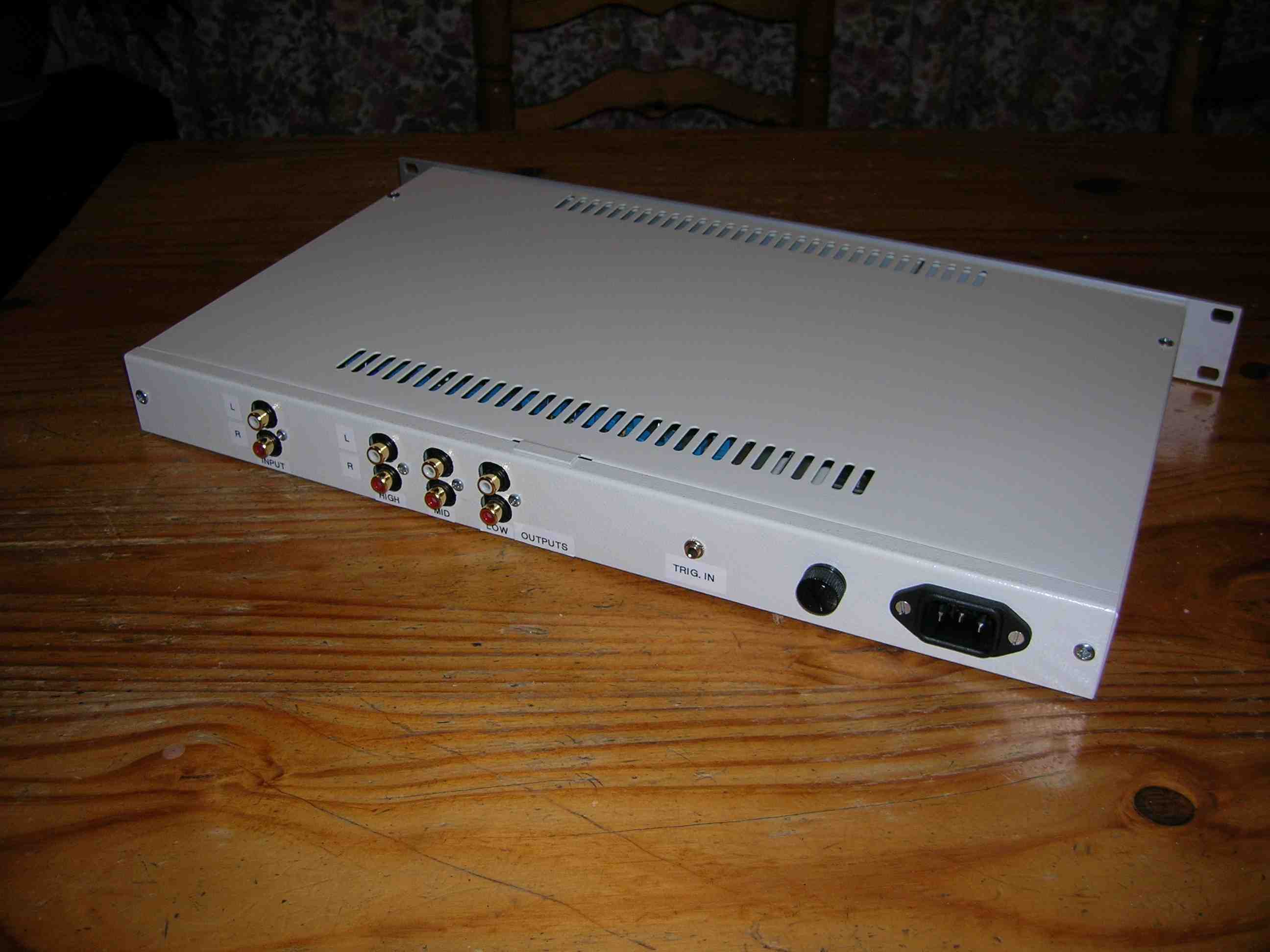
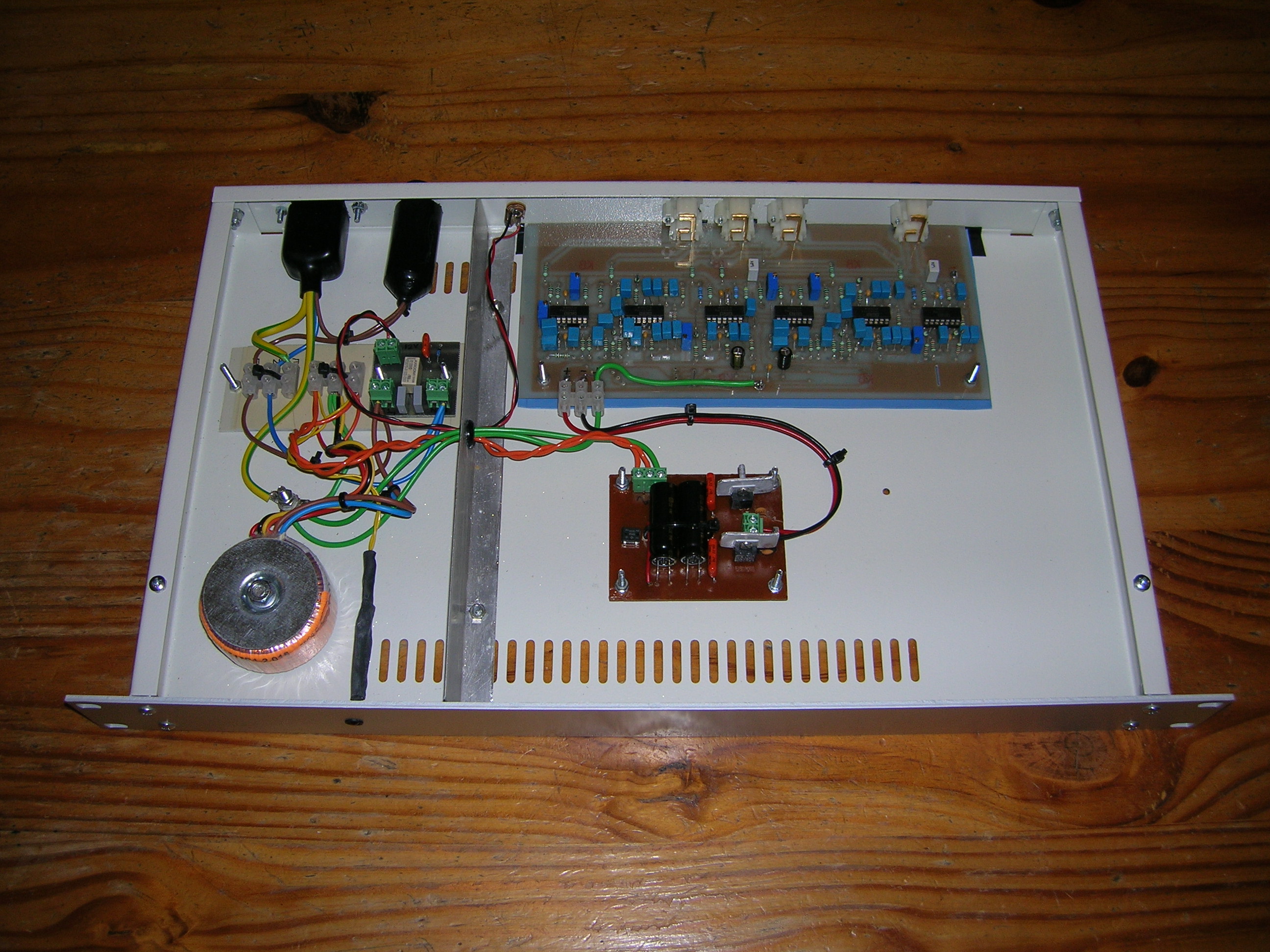
I opted to buy a ready-made PCB for the crossover rather than attempt to make my own. The Quartets have crossover frequencies of 250 Hz and 2.3 kHz, so some component value changes from the Silicon Chip article were necessary to make the active crossover match this. I had decided to use audiophile-grade components in the construction as much as possible, which meant using polypropylene capacitors for the filter sections. These are considerably larger than the polyester ones that were specified in the original article so some of them had to be soldered in on Veropin ‘stilts’ to make them fit in. However I don’t think that the end-result is too untidy as can hopefully be seen in the photo. I also decided to use Burr-Brown OPA4227 quad low-noise op-amps in place of the TL074s; these were about ten times the price but there’s no point in scrimping if you’re going to all this trouble. The whole thing is contained in a 1U rack-mounting case that fits neatly out of the way on the floor.

Some things didn’t quite go to plan and changes had to be made, but more of this later …
Once constructed, a brief test with an old amplifier and a bit of freeware PC signal generator software called SigJenny verified that the crossover was doing when it was supposed to do. The time had now come to start modifying the Quartets to remove the passive crossovers.
Taking my lovely loudspeakers apart was not something I was particularly looking forward to doing but needs must. Fortunately the crossover is easy to remove as it’s screwed directly onto the back of the terminal panel at the rear:
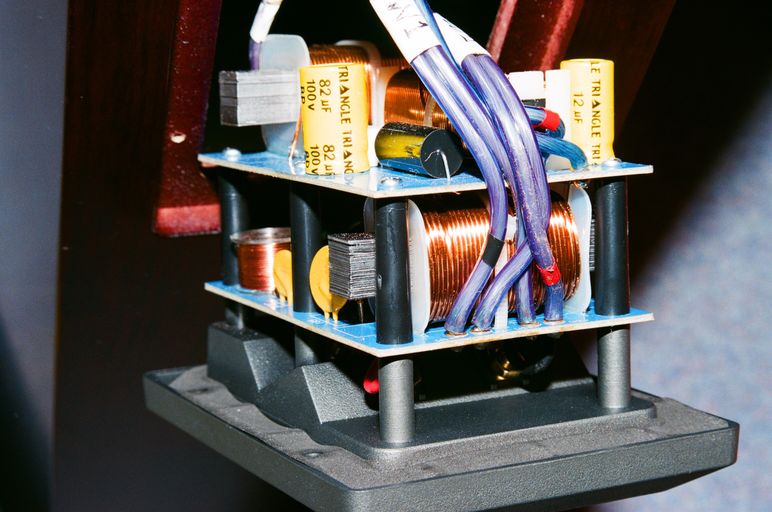
I wanted to be able to restore everything back to how it was in case I ever decide to sell the Quartets in the future so I carefully identified each driver’s connections and, most importantly, their polarity. Finally I unsoldered the cables and removed the crossovers.
The passive crossovers were safely boxed up and stored away up in the loft. The terminal panels of the Quartets already had two pairs of terminals installed for bi-wiring or bi-amping, but of course I needed a third pair of terminals for the extra driver so I began the task of modifying the terminal panels. I wanted the whole thing to look professional so I opted to replace the existing Triangle terminals at the same time so that all three pairs were of the same type. I chose Michell Engineering’s ‘Big Mother’ binding posts. They are excellent quality and they look the duck’s nuts as well.
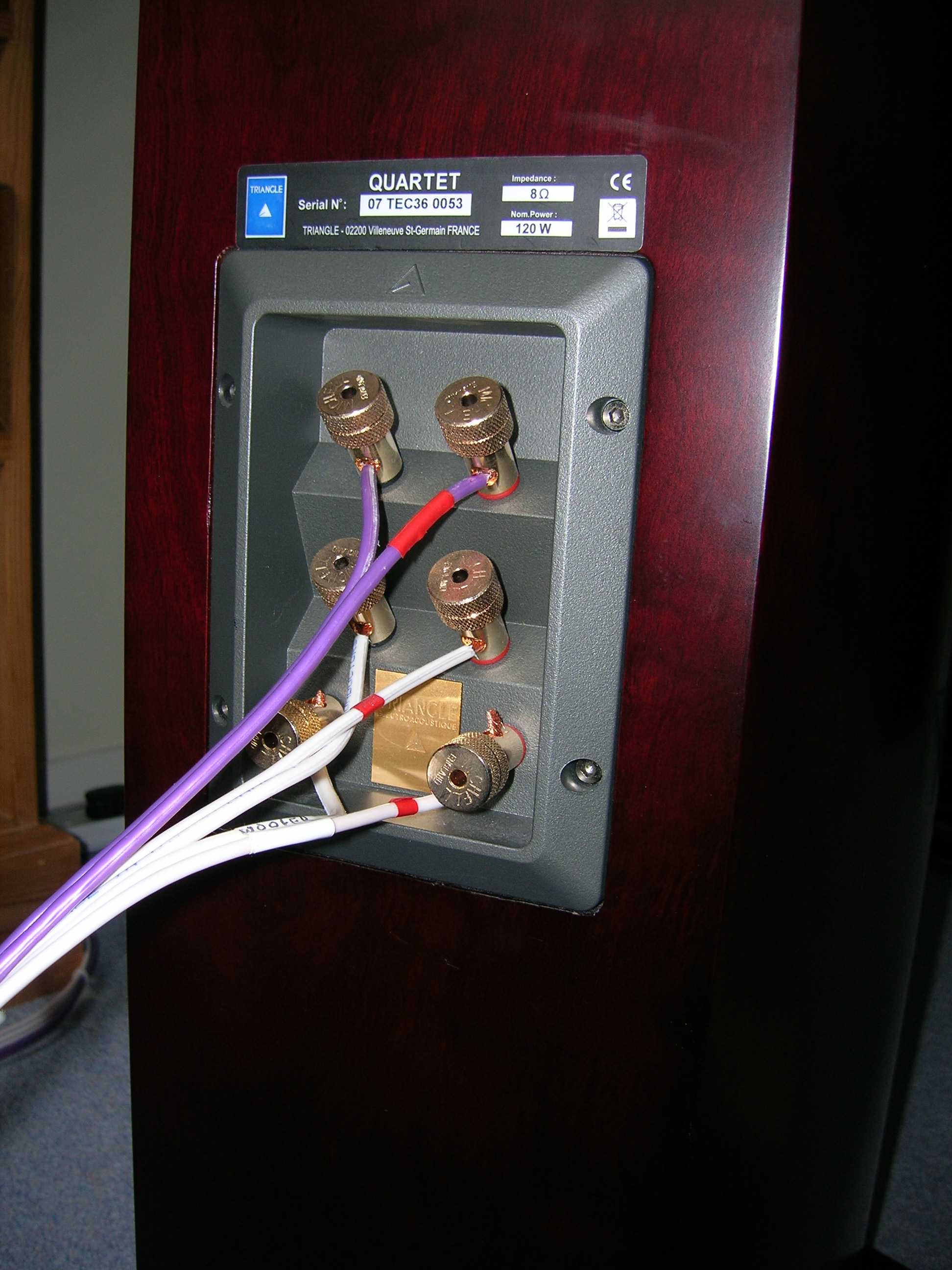
The original Triangle terminals on the panels were connected to the passive crossovers using small gold-plated tabs. There are two ‘runners’ moulded into the plastic behind each terminal post on the panel to take the tab. To provide a flat surface on which to tighten down the nuts for the new Big Mother terminals I had to fashion a set of shims out of some 0.8 mm brass strip that I bought from a modelling supplier on eBay. These shims fit between the plastic runners; you can just see two of them in the photo below:
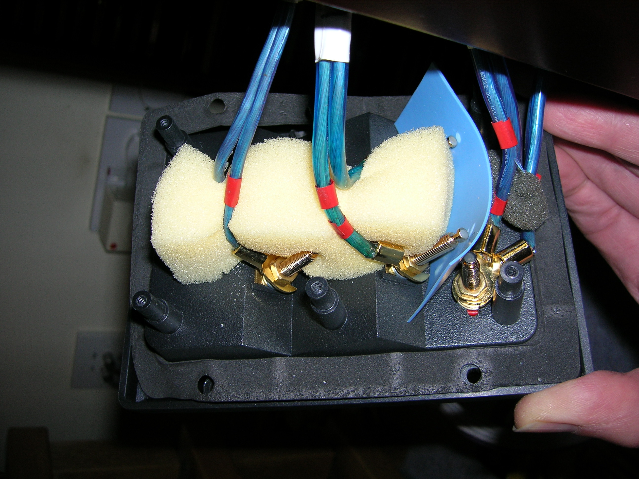
The shims can just be seen on the mounting posts mounted at a 45-degree angle. The cables to the drivers then attach to the terminals using some gold-plated spade terminals also sourced from eBay. I would rather have used gold-plated ring terminals for these but I couldn’t find any suppliers of them; if anyone knows where I can get some then please get in touch! Ring terminals might also allow me to get rid of those rather untidy bits of plastic and foam padding that I put in to prevent the terminals from shorting out against each other.
Now for the tricky bit. How to balance the individual speaker drivers to give a uniform sound. The crossover circuit has preset potentiometers to adjust the individual outputs from each filter, so it should be possible to tweak these to account for the different sensitivities of the drive units. My first idea was to use a microphone plugged into an old Mackie mixer with a VU meter to measure the sound level from the loudspeakers while feeding in an input signal from SigJenny and sweeping the frequency range. However this failed fairly miserably. As soon as I moved the microphone just a short distance the VU meter fluctuated all over the place. I think there are probably just too many room resonances and standing waves present in the average lounge to do this properly. So on to plan B …
I was quite pleased with this idea. At any one crossover frequency the two associated Linkwitz-Riley filters have identical output levels and the signals are in phase. The Arcam amplifiers all have switches with which it’s possible to turn the speaker outputs on or off. So the plan was to feed in a signal at exactly the right frequency for the first crossover point between the bass and mid-range drivers (i.e. 250 Hz), and then use the speaker output switches to do a simple A-B comparison between the two amps. If the sensitivities of the drivers were equal the sound level would appear to be the same when switching between them. Of course it’s unlikely that the sensitivities of the drivers would be the same, but by tweaking the appropriate potentiometers in the crossover the levels could be equalised. This process could then be repeated for the second crossover frequency of 2.3 kHz for the mid-range unit and tweeter. Simple! It could be done by ear and it was foolproof. I enlisted the help of a willing relative with one of his daughters providing a set of younger ears. After much listening everything was balanced up. The result? It sounded awful …
I still don’t understand why this did not work but there was no arguing with the fact that the sound was dull and lifeless. Rod Elliott says on his web site that it is surprisingly easy to balance up active crossovers with the aid of a good set of headphones and he is actually absolutely right. So this became plan C. I used my Sennheiser HD650s to compare headphones with loudspeakers and ran through several different CD tracks adjusting the crossover potentiometers as I went along until I thought I had the balance right.
The following table shows the eventual gain settings that I ended up with. I deliberately left the mid-range gain set to unity as trying to adjust all three gains would have got a bit too complicated:
| Filter | Gain (factor) | Gain (dB) |
|---|---|---|
| Low-pass | 1.83 | +5.2 |
| Mid-range | 1.00 | 0 |
| High-pass | 0.60 | -4.4 |
At this point although things were adjusted quite nicely two problems were evident:
- There was a lot of mains hum.
- There was a curious audible high-pitched whistling noise.
I know from past experience with DIY hi-fi gear that mains hum can be very difficult to get rid of. Eventually, after trying many different things to identify where the hum was coming from, I moved the power supply components off the main PCB and onto a separate small custom-made PCB with proper star earthing. This solved the problem.
The high-pitched whistle was solved by accident. The digital display on the A32 amp can be either on full brightness, half brightness or switched off. I discovered that the whistle only appeared when the display was on half brightness. So not surprisingly, it is now set to be on full brightness! I may try to tackle this at some point in the future if I’m short of things to do – it must be some low-pass filtering required somewhere – but at the moment it can stay the way it is.
Now that everything was essentially finished, it just needed a good testing session with a set of unbiased ears. My mate with the Arcam contacts fortunately shares a similar taste in music to me and he was willingly enlisted for this task. We spent a memorable Friday afternoon drinking beer and creating a lot of noise, which I’m proud to say could be heard halfway up the street. After refuelling on food (and more beer) courtesy of the local curry house I think we both agreed that the crossover potentiometers were finally set correctly …
However there was still room for improvement. Fixed-voltage regulators such as the 7800/7900 series have a bit of a reputation for being noise generators, so I decided to rebuild the power supply using better quality variable-voltage LM317 & LM337 devices. This meant designing a slightly more complicated PCB but the new one still fits into the same space as shown in the first photo above.
The end result of all this? The Quartets sounded good before I hacked around with them but I think they sound fabulous now. The sound is so detailed and the bass has a real punch that probably only a dedicated amplifier could deliver. I did wonder at times whether the whole adventure was worth the effort but I’m glad I did it now.
Folk with sharp eyes might notice that in the first two photos above there is a small PCB mounted near the mains fuse and a ‘TRIG IN’ jack socket on the back of the unit. This was an abortive attempt to make the unit power up from the 12V remote power output on the A32 amp. This does work, but unfortunately for reasons best known to Arcam the two P38 power amplifiers do not power up from cold with the speaker outputs active (unlike the A32). They only do this if they are brought out of standby. A quick chat with someone in the Arcam technical department revealed that this is by design – why I don’t know. There is also a time lag before the P38s activate from the 12V input, so the crossover would have been the last piece of equipment to power up. I dread to think of the various switch-on noises that would have been produced by this so I decided to bypass the 12V input and wire the crossover so that it powers up as soon as it’s plugged into the mains.
Finally I wanted the system to look good as well as sound good. A higgledy-piggledy jumble of cabinets and cables would never be allowed by the Boss. I got hold of a set of oak racking units made by Hi-Fi Racks and supplied by The Audio File in Bishops Stortford (which became part of Sevenoaks Hi-Fi). These beautiful units aren’t cheap but they are expandable and can also be specified with any leg length you want. I opted for a set of short legs for the bottom stage so that I could squeeze the crossover in on the floor:
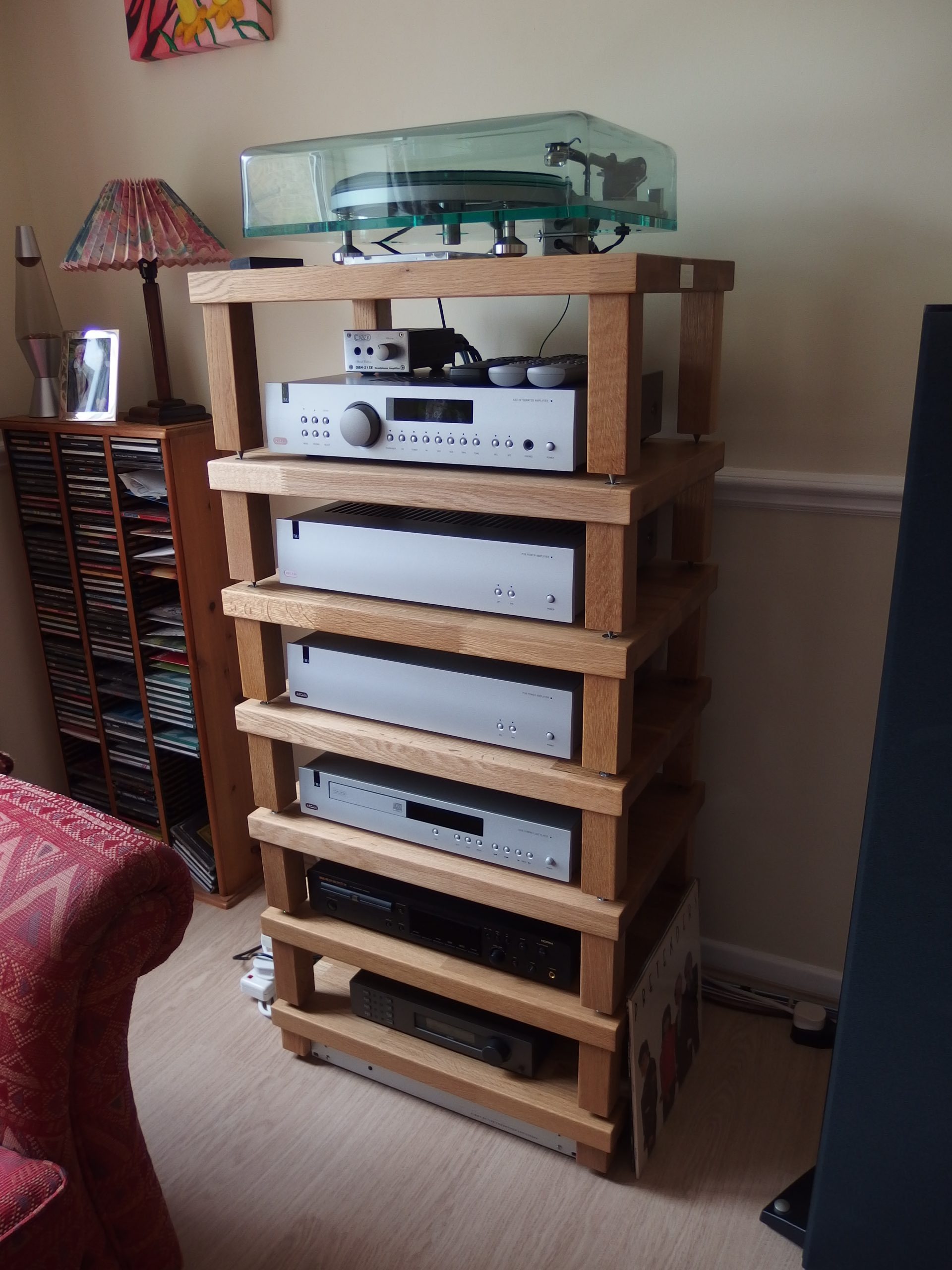
You can see the front panel of the active crossover on the floor underneath the Quad FM4 tuner on the bottom shelf. The racking units have certainly made quite a monster tower-full of hi-fi gear but at least it’s a talking point when visitors come round!
The cable is QED 2.50 mm2 79-strand Performance Original OFC loudspeaker cable. In the days before I had the Triangles I was using just the purple-coloured cable for each speaker. I decided to continue using the original cable for the tweeters and buy additional cable for the bass and mid-range drivers. QED manufactures a bi-wire version of the 79-strand cable which is ideal, except for the fact that it’s only available now in pearlescent white. I did consider replacing the purple cable to have everything colour-coordinated, but luckily common sense prevailed …
Last but not least I would like to thank Thomas Robert at Triangle France for his help and technical advice on loudspeaker driver sensitivities and generally how to butcher his company’s products. Je vous remercie, Thomas.